


The THOMSON CHASSIS ICC5 Is a highly engineered chassis (see pictures).
It was introducing high integration of advanced and high precision functions.
It's introducing all digital control of all circuits, from tuning to video matrix and audio.
It was fitted in a very high number of models with screen formats varying from 20 to 32 Inches.
It has known a high rate of improvements and add ons fetures and further functions.
The version here in collection is the first marketed in 1985 when the ICC5 was developed.
It was alomost immediately replaced by a further version (5110) which eliminates the reset ic but keeping the basic design here shown.
It has a layout design which is very complex due to high engineering on signal path toghether with integration needings.
Functionally they run very well and stable but it was showing the highest rate of failures caused by dry joint evn almost immediately when new !! !!
To run these in reliable way you have to basically rework all the PCB Joint !!
Quality of components it's very high, all parts here pictured are original from 1985.
Picture produced by this chassis is excellent and this is expecially coming from the accurate and high performed video signal processing.
Audio / Sound section is realized with ITT DIGIVISION SOUND CHIPSET, and by this way DIGITAL processed.
The ICC5 got a bad press but they were an advanced design and unusual for the time for a European chassis in that they didn't make widespread use of Philips techniques or components.B&O sets have used it like the MX3000, MX4500 and MX5000. B&O had also used the previous ICC3 in the MX2000 and the M20, so they weren't much of a culture shock - the removal of the big mains transformer that the ICC3 had was clearly the key design goal.I found the chassis to be reasonably reliable after reworking and well laid out in general maybe a bit too compact, there were a few quirks without a doubt , the E-W stage once sorted with modified coil etc. wasn't so unreliable after all. The PCB layout was one of the most complex design almost like a computer board. It was only when they aged you started to get some real weird faults. The ICC7/8 were a lot more conventional circuitry wise, and posed few real problems. The ICC9 and IDC2 were not very reliable at all, possibly the least reliable of the lot, the IKC2 was a close second! Personally i disliked the IKC2.This models series are the last featuring the THOMSON CHASSIS ICC5, replaced with THOMSON ICC7, ICC8 SERIES.
COLOR TV SCANNING AND POWER SUPPLY PROCESSOR TEA2029C
DESCRIPTION
The TEA2029C is a complete (horizontal and vertical)
deflection proc
essor with secondary to primarySMPS control for color TV sets.
DEFLECTION .CERAMIC 500kHz RESONATOR FREQUENCY
REFERENCE .NO LINE AND FRAME OSCILLATOR ADJUSTMENT
.DUAL PLL FOR LINE DEFLECTION .HIGH PERFORMANCE SYNCHRONIZATION .SUPER SANDCASTLE OUTPUT .VIDEO IDENTIFICATION CIRCUIT .AUTOMATIC 50/60Hz STANDARD IDENTIFICATION
.EXCELLENT INTERLACING CONTROL .SPECIALPATENTED FRAME SYNCHRO DEVICE
FOR VCR OPERATION .FRAME SAW-TOOTH GENERATOR .FRAME PHASE MODULATOR FOR THYRISTOR
SMPS CONTROL .ERROR AMPLIFIER AND PHASE MODULATOR
.SYNCHRONIZATION WITH HORIZONTAL
DEFLECTION .SECURITY CIRCUIT AND START UP PROCESSOR.
GENERAL DESCRIPTION
This integrated circuit uses I2L bipolar technology
and combines analog signal processing with digital
processing.
Timing signals are obtainedfrom a voltage-controlled
oscillator (VCO) operatingat 500KHzby means
of a cheap ceramic resonator. This avoids the
frequency adjustment normally required with line
and frame oscillat
ors.A chain of dividers and appropriate logic circuitry
produce very accurately defined sampling pulses
and the necessary timing signals.
The principal functions implemented are :
- Horizontal scanning processor.
- Frame scanning processor. Two applications are
possible :
- D Class : Power stage using an external
thyristor.
- B Class : Powerstageusing an externalpower
amplifier with fly-back generator
such as the TDA8170.
- Secondary switch mode power regulation.
The SMPS output synchronize a primary I.C.
(TEA2260/61)at the mains part.
This concept allows ACTIVE STANDBY facilities.
- Dual phase-locked loop horizontal scanning.
- High performance frameand line synchronization
with interlacing control.
- Video identification circuit.
- Super sandcastle.
- AGC key pulse output.
- Automatic 50-60Hz standard identification.
- VCR input for PLL time constant and frame synchro
switching.
- Frame saw-tooth generator and phase modulator.
- Switchingmode regulated power supplycomprising
error amplifier and phase modulator.
- Security circuit and start-up processor.
- 500kHzVCO
The circuit is supplied in a 28 pin DIP case.
VCC = 12V.
Synchronization Separator
Line synchronization separator is clamped to
black level of input video signal with synchronization
pulse bottom level measurement.
The synchronization pulses are divided centrally
between the black level and the synchronization
pulse bottom level, to improve performance on
video signals in noise conditions.
Frame Synchronization
Frame synchronization is fully integrated (no external
capacitor required).
The frame timing identification logic permits automatic
adaptation to 50 - 60Hz standards or non-interlaced
video.
An automatic synchronization window width system
provides :
- fast frame capture (6.7ms wide window),
- good noise immunity (0.4ms narrow window).
The internal generator starts the discharge of the
saw-tooth generator capacitor so that it is not disturbed
by line fly back effects.
Thanks to the logic control, the beginning of the
charge phase does not depend on any disturbing
effect of the line fly-back.
A 32ms timing is automatically applied on standardized
transmissions, for perfect interlacing.
In VCR mode, the discharge time is controlled by
an internal monostable independent of the line
frequency and gives a direct frame synchronization.
Horizontal Scanning
The horizontalscanningfrequencyis obtainedfrom
the 500kHz VCO.
The circuit uses two phase-locked loops (PLL) :
the first one controls the frequency, the second one
controls the relative phase of the synchronization
and line fly-back signals.
The frequency PLL has two switched time constants
to provide
:- capture with a short time constant,
- good noise immunity after capture with a long
time constant.
The output pulse has a constant duration of 26ms,
independent of VCC and any delay in switching off
the scanning transistor.
Video Identification
The horizontal synchronization signal is sampled
by a 2ms pulse within the synchronization pulse.
The signal is integrated by an external capacitor.
The identification function provides three different
levels :
- 0V : no video identification
- 6V : 60Hz video identification
- 12V : 50Hz video identification
This information may be used for timing research
in the case of frequency or voltage synthetizer type
receivers, and for audio muting.
Super Sandcastle with 3 levels : burst, line flyback,
frame blanking
In the event of vertical scanning failure, the frame
blanking level goes high to protect the tube.
Frame blanking time (start with reset of Frame
divider) is 24 lines.
VCR Input
This provides for continuous use of the short time
constant of the first phase-locked loop (frequency).
In VCR mode, the frame synchronization window widens out to a search window and there is no
delay of frame fly-back (direct synchronization).
Frame Scanning
FRAME SAW-TOOTH GENERATOR. The current
to charge the capacitoris automatically switched to
60Hz operation to maintain constant amplitude.
FRAME PHASE MODULATOR (WITH TWO DIFFERENTIAL
INPUTS). The output signal is a pulse
at the line frequency, pulse width modulatedby the
voltage at the differential pre-amplifier input.
This signal is used to control a thyristor which
provides the scanning current to the yoke. The
saw-tooth output is a low impedance,however, and
can therefore be used in class B operation with a
power amplifier circuit.
Switch Mode Power Supply (SMPS) Secondary
to Primary Regulation
This power supply uses a differential error amplifier
with an internal reference voltage of 1.26V and a
phase modulator operating at the line frequency.
The powertransistor is turnedoff bythe falling edge
of the horizontal saw-tooth.
The ”soft start” device imposes a very small conduction
angle on
starting up, this angle progressivelyincreases to its nominal regulation value.
The maximum conductionangle may be monitored
by forcing a voltage on pin 15. This pin may also
be used for current limitation.
The outputpulse is sent to the primaryS.M.P.S. I.C.
(TEA2261) via a low cost synchro transformer.
Security Circuit and Start Up Processor
When the security input (pin 28) is at a voltage
exceeding 1.26V the three outputs are simultaneously
cut off until this voltagedrops below the 1.26V
threshold again. In this case the switch mode
power supply is restarted by the ”soft start” system.
If this cycle is repeated three times, the three
outputs are cut off definitively. To reset the safety
logic circuits, VCC must be zero volt.
This circuit eliminates the risk to switch off the TV
receiver in the event of a flash affecting the tube.
On starting up, the horizontal and vertical scanning
functions come into operation at VCC = 6V. The
power supply then comes into operation progressively.
On shutting down, the three functions are interrupted
simultaneously after the first line fly-back.
CHASSIS THOMSON ICC5 APPLICATION INFORMATION ON FRAME
SCANNING IN SWITCHED MODE:
Fundamentals (see Figure 80)
The secondary winding of EHT transformer provides
the energy required by frame yoke.
The frame current modulation is achieved by
modulating the horizontal saw-tooth current and
subsequent integration by a ”L.C” network to reject
the horizontal frequency component.

General Description
The basic circuit is the phase comparator ”C1”
which compares the horizontal saw-tooth and the
output voltage of Error Amplifier ”A”.
The comparator output will go ”high” when the
horizontal saw-tooth voltage is higher than the ”A”
output voltage. Thus, the Pin 4 output signal is
switched in synchronization with the horizontal frequency
and the duty cycle is modulated at frame
frequency.
A driver stage delivers the current required by the
external power switch.
The external thyristor provides for energy transfer
between transformer and frame yoke.
The thyristor will conduct during the last portion of
horizontal trace phase and for half of the horizontal
retrace.
The inverse parallel-connected diode ”D” conducts
during the second portion of horizontal retrace and
at the beginning of horizontal trace phase.
Main advantages of this system are :
- Power thyristor soft ”turn-on”
Once the thyristor has been triggered, the current
gradually rises from 0 to IP, where IP will reach
the maximumvalue at the end of horizontal trace.
The slope current is determined by, the current
available through th
e secondary winding, theyoke impedance and the ”L.C.” filter characteristics.
- Power thyristor soft ”turn-off”
The secondary output current begins decreasing
and falls to 0 at the middle of retrace. The thyristor
is thus automatically ”turned-off”.
- Excellent efficiency of power stage dueto very
low ”turn-on” and ”turn-off” switching losses.
Frame Flyback
During flyback, due to the loop time constant, the
frame yoke current cannot be locked onto the
reference saw-tooth. Thus the output of amplifier
”A” will remain high and the thyristor is blocked.
The scanning current will begin flowing through
diode ”D”. As a consequence, the capacitor ”C”
starts charging upto the flyback voltage.The thyristor
is triggeredas soon as the yoke current reaches
the maximum positive value.
TDA4443 MULTISTANDARD VIDEO IF AMPLIFIER
DESCRIPTION
The TDA4443 is a Video IF amplifier with standard
switch for multistandard colour or monochromeTV
sets, and VTR’s.
SWITCHING OFF THE IF AMPLIFIER WHEN
OPERATING IN VTR MODE .DEMODULATION OF NEGATIVE OR POSITIVE
IF SIGNALS. THE OUTPUT REMAINS
ON THE SAME POLARITY IN EVERY CASE .IF AGC AUTOMATICALLY ADJUSTED TO
THE ACTUALSTANDARD .TWO AGC POSSIBILITIES FOR B/G MODE :
1. GATED AGC
2. UNGATED AGC ON SYNC. LEVEL AND
CONTROLLED DISCHARGE DEPENDENT
ON THE AVERAGE SIGNAL LEVEL FOR VTR
AND PERI TV APPLICATIONS
FOR STANDARD L : FAST AGC ON PEAK
WHITE BY CONTROLLED DISCHARGE .POSITIVE OR NEGATIVE GATING PULSE .EXTREMELY HIGH INPUT SENSITIVITY .LOW DIFFERENTIAL DISTORTION .CONSTANT INPUT IMPEDANCE .VERY HIGH SUPPLY VOLTAGE REJECTION .FEW EXTERNAL COMPONENTS .LOW IMPEDANCE VIDEO OUTPUT .SMALL TOLERANCES OF THE FIXED VIDEO
SIGNALAMPLITUDE .ADJUSTABLE, DELAYED AGC FOR PNP
TUNERS.
GENERAL DESCRIPTION
This video IF processing circuit integrates the following
functional blocks : .Three symmetrical, very stable, gain controlled
wideband amplifier stages - without feedback
by a quasi-galvanic coupling. .Demodulator controlled by the picture carrier .Video output amplifier with high supply voltage
rejection .Polarity switch for the video output signal .AGC on peak white level .GatedAGC .Discharge control .Delayed tuner AGC .At VTR Reading mode the video output signal
is at ultra white level.
TDA4445A SOUND IF AMPLIFIER
.QUADRATURE INTERCARRIER DEMODULATOR
.VERY HIGH INPUT SENSITIVITY .GOODSIGNALTO NOISE RATIO .FAST AVERAGINGAGC .IF AMPLIFIER CAN BE SWITCHED OFF FOR
VTR MODE .GOODAM SUPPRESSION .OUTPUT SIGNAL STABILIZED AGAINST
SUPPLY VOLTAGE VARIATIONS .VERY FEW EXTERNAL COMPONENTS
DESCRIPTION
TDA4445A:
Sound IF amplifier, with FM processing for quasi
parallel sound system.
TDA4445B:
Sound IF amplifier, with FM processing and AM
demodulator, for multi-standard sound TV appliances.
TDA4445Badditionnal :
Bistandard applications (B/G and L)
No adjustment of the AM demodulator
Low AMdistortion.
GENERAL DESCRIPTION
This circuit includes the following functions : .Three symmetrical and gain controlled wide
band amplifier stages, which are extremely stable
by quasiDC coupling without feedback. .Averaging AGC with discharge control circuit .AGC voltage generator
Quasi parallel sound operation : .High phase accuracy of the carrier signal processing,
independentfrom AM .Linear quadrature demodulator .Sound-IF-amplifier stage with impedance converter
AM-Demodulation (only TDA4445B) : .Carrier controlled demodulator .Audio frequency stage with impedance converter
.Averaging low passAGC.
CHASSIS ICC5 Switched mode power supply transformer

A switched mode power supply transformer, particularly for a television receiver, including a primary winding and a secondary winding with the primary winding and the secondary winding each being subdivided into a plurality of respective partial windings. The partial windings of the primary lie in a first group of chambers and the partial windings of the secondary lie in a second group of chambers of a chamber coil body, and the chambers of both groups are nested or interleaved with one another.
1. A switched mode power supply transformer, particularly for a television receiver, comprising in combination:
a primary winding and a secondary winding, with said primary winding being subdivided into three partial windings and said secondary winding being subdivided into two partial windings;
a chamber coil body having a plurality of chambers;
said partial windings of said primary winding being disposed only in a first group of said chambers, and said partial windings of said secondary winding being disposed only in a second group of said chambers, with each of said partial windings being disposed in a respective one of said chambers;
said chambers of said first group being interleaved with said chambers of said second group such th
at they alternate in sequence with said primary partial windings and said secondary partial windings being alternatingly disposed in five successive said chambers, so as to generate the major operating voltage at said secondary winding; an additional secondary winding for generating a further operating voltage, said additional secondary winding likewise being subdivided into a plurality of partial windings; and,
said partial windings of said additional secondary winding are disposed only in respective said chambers of said second group below any of said partial windings of said secondary winding.
2. A transformer as defined in claim 1 wherein the total number of said chambers is six.
3. A transformer as defined in claim 1 wherein the width of the narrowest of said chambers is approximately 1 mm.
4. A transformer as defined in claim 1 or 2 wherein the widths of said chambers are different.
5. A transformer as defined in claim 1 or 2 wherein the total width of all of said chambers is only approximately 20 mm, whereby a flat and optimally coupled transformer is realized.
6. A transformer as defined in claim 1 wherein said additional secondary winding provides an operating voltage for a load which has a fluctuating current input.
7. A transformer as defined in claim 1 wherein said partial windings of said additional secondary winding are connected in parallel.
8. A transformer as defined in claim 1 wherein said partial windings of said primary winding are connected in series.
9. A transformer as defined in claim 1 or 8 wherein said partial windings of said secondary winding are connected in series.
10. A transformer as defined in claim 1 fur
ther comprising a plurality of auxiliary primary windings disposed in one chamber of said first group which is disposed in approximately the center of said first group and above the said partial winding of said primary winding disposed in said one chamber of said first group. 11. A transformer as defined in claim 1 wherein all of said partial winding disposed in said chambers of both said groups are wound with wire having the same diameter.
12. A switched mode power supply transformer as defined in claim 1 or 10 wherein: said coil body has six of of said chambers; said additional secondary winding is subdivided into three said partial windings; and two of said partial windings of said additional secondary winding are disposed below respective ones of said partial windings of said secondary winding and the third said partial winding of said additional secondary winding is disposed in the sixth said chamber.
13. A switched mode power supply transformer as defined in claim 10 further comprising at least one further secondary winding disposed in one of said chambers of said second group above any partial secondary winding present in said one of said chambers.
14. A switched mode power supply transformer, particularly for a television receiver, comprising in combination:
a primary winding and a secondary winding, with said primary winding and said secondary winding each being subdivided into a plurality of partial windings;
a chamber coil body having a plurality of chambers;
said partial windings of said primary winding being disposed only in a first group of said chambers, and said partial windings of said secondary winding being disposed only in a second group of said chambers with each of said partial windings being disposed in a respective one of said chambers;
said chambers of said first group being interleaved with said chambers of said second group such that said primary partial windings and said secondary partial windings are alternatingly disposed in successive said chambers, so as to generate the major operating voltage at said secondary winding;
an additional secondary winding for generating a further operating voltage, said additional secondary winding likewise being subdivided into a plurality of partial windings, and said partial windings of said additional secondary winding are disposed only in respective said chambers of said second group below any of said partial windings of said secondary winding.
15. A switched mode power supply transformer as defined in claim 1 or 14 wherein each of said partial windings of said primary winding contains the same number of turns and each of said partial windings of said secondary winding contains the same number of turns.
Description:
BACKGROUND OF THE INVENTION
The present invention relates to a switched mode power supply transformer, particularly for a television receive r.
r.
In communications transmissions devices, particularly in television receivers, it is known to effect the desired dc decoupling from the mains by means of so-called switched mode power supply transformers. Such switched mode power supply transformers are substantially smaller and lighter in weight than a mains transformer for the same power operating at 50 Hz, because they operate at a significantly higher frequency of about 20-30 kHz. Such a switched mode power supply transformer (hereinafter called SMPS transformer) generally includes a primary side with a primary winding serving as the operating winding for the switch and further additional auxiliary windings, as well as a secondary side with a secondary winding for generating the essential operating voltage and possibly further additional windings for generating further operating voltages of different magnitude and polarity. The secondary and primary are insulated from one another as prescribed by VDE and have the necessary dielectric strength so that there is no danger of contact between voltage carrying parts on the secondary. A switched mode power supply (SMPS) circuit for a tv-receiver is described in U.S. Pat. No. 3,967,182, issued June 29, 1976.
A further requirement placed on such an SMPS transformer is that the stray inductance at least of the primary winding and of the secondary winding should be as small as possible. With too high a stray inductance, a transient behavior may develop during the switching operation which would not assure optimum switch operation of the switching transistor connected to the primary winding and would endanger this transistor by taking on too much power. Moreover, an increased stray inductance undesirably increases the internal resistance of the voltage sources for the individual operating voltages.
It is known to design the windings for such transformers as layered windings. Such layered windings, however, contain feathered intermediate foil layers and, after manufacture, generally require that the coil or the complete transformer be encased in order to insure VDE safety. Use as a chamber winding in television receivers presently does not take place because of the problems to be discussed below. A chamber winding would have the particular adv antage that it could be wound more easily and economically by automatic machines. when using a chamber winding for a switched mode power supply, the detailed insulation between the primary and the secondary would be realized initially by two chambers with one of these chambers being filled only with the windings of the primary and the other of these chambers being filled only with the windings of the secondary. However, with such an arrangement there would exist only slight coupling between the primary and the secondary and thus an undesirably high stray inductance. If, on the other hand, the number of chambers were selected to be substantially larger, the transformer becomes more expensive and unnecessarily large. Moreover, a larger core would be required. Consequently, in the past, no television receiver has been introduced that included an SMPS transformer.
SUMMARY OF THE INVENTION
It is the object of the present invention to provide an SMPS transformer designed in the chamber wound technique which permits economical automatic winding, i.e. can be wound with but a single type of wire, has a structure which is spatially narrow and as flat as possible, provides the required insulation between the primary and secondary windings, and has a low stray inductance. The transformer should not be encased or saturated and nevertheless should produce no interfering noise during operation. The transformer should be able to be held in a circuit board without mechanical aids merely by its connecting terminals which are soldered to the circuit board.
The above object is basically achieved according to the present invention in that the transformer for a switched mode power supply, particularly for a television receiver, comprises: a primary winding and a secondary winding with the primary and secondary windings each being subdivided into a plurality of partial windings; and a chamber coil body with a plurality of chambers; and wherein the partial windings of the primary winding are disposed in a first group of chambers of the coil body, the partial windings of the secondary winding are disposed in a second group of chambers of the coil body, and the chambers of the first and second groups are interleaved.
Due to the fact that the individual windings or partial windings of the primary are disposed only in chambers of the first group and the windings or partial windings of the secondary are disposed only in chambers of the second group, i.e. primary and secondary are distributed to separate chambers, the necessary dielectric strength between primary and secondary is assured. By dividing each of the primary and secondary windings to a respective plurality or group of chambers and, due to the interleaved or nested arrangement of the chambers of the primary and the secondary, the desired fixed coupling between primary and secondary, and thus the desired low stray inductance at the primary and secondary, are realized. It has been found that a total number of chambers in the order of magnitude of six constitutes an economically favorable solution. With a smaller number of chambers, the coupling between primary and secondary is reduced. With a larger number of chambers, however, either the individual chambers become too small or the entire transformer, and particularly the core, become too large.
BRIEF DESCRIPTION OF THE DRAWINGS
FIG. 1 is a circuit diagram for a preferred embodiment of a switched mode power supply transformer according to the invention.
FIG. 2 is a schematic partial sectional view showing the distribution of the individual windings of FIG. 1 to different chambers according to the invention.
DETAILED DESCRIPTION OF THE PREFERRED EMBODIMENT
FIG. 1 shows a transformer intended for a switched mode power supply for a television receiver with a power output between 40 and 150 watts. The transformer includes a primary side P and a secondary side S which, while maintaining the required dielectric strength of, for example, 10,00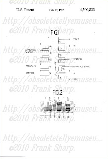 0 V, are galvanically decoupled or separated from one another. The primary side P includes a primary winding 1 which, as the operating winding, will lie in the collector circuit of a switching transistor switched at about 20-30 kHz. The primary winding 1 is divided into three partial windings 1a, 1b and 1c which are connected in series. When utilized in a television receiver, the beginning of partial winding 1a and the end of partial winding 1c are connected into the collector circuit of the switching transistor, while the taps between the partial windings 1a-1b and 1b-1c are not utilized, but rather form supporting points for the connection of the terminals of the partial windings. The primary side P also includes an additional winding 3 which feeds the feedback path with which the primary winding 1a-1c is designed as a self-resonant circuit. Moreover, the primary side P includes an additional winding 4 for regulating the moment of current flow in the switching transistor in the sense of stabilizing the amplitude of the output voltages on the secondary side S.
The secondary side S initially includes the secondary winding 2 from which is obtained, via a rectifier circuit (not shown), the main operating voltage U1. The secondary winding 2 is divided into two series connected partial windings 2a and 2b. Additionally, the secondary winding S includes a winding 5 for generating an operating voltage for the video amplifier and a further winding 6 for generating the operating voltage for the vertical deflection stage of a television receiver. Moreover, an additional secondary winding 7 is provided from which, after rectification, the operating voltage or the audio output stage of the receiver is obtained. Winding 7 comprises three partial windings 7a, 7b, 7c which are connected in parallel. The audio output stage of a television receiver has a greatly fluctuating current input between 50 mA and 1000 mA so that the load of the secondary side S varies considerably. This variation in load may effect an undesirable change in the operating voltage U1 which also influences the horizontal deflection amplitude. This undesirable dependency can be reduced in that the coupling between winding 7 and winding 4 is dimensioned greater, for regulating purposes, than the coupling between winding 2 and winding 4. This solution is described in greater detail in Federal Republic of Germany Offenlegungsschrift (laid open application) DE-OS No. 2,749,847 of May 10, 1979. This increased coupling between windings 7 and 4 is realized in the present case by the three parallel connected windings 7a, 7b, 7c. Finally, the secondary S includes a further winding 8 which serves to generate, after rectification, a negative operating voltage of -30 V.
FIG. 2 shows one half of the chamber coil body 9 for the individual windings of FIG. 1, with the body 9 including a total of six chambers 10. The size and particularly the widths of the individual chambers 10 can vary with respect to one another and the widths may all be different. Preferably, the width of the narrowest chamber 10 is about 1 mm and the total width of all six chambers is only approximately 20 mm so as to realize a flat and optimally coupled transformer.
As shown, one third of the primary winding 1, in the form of respective partial windings 1a, 1b and 1c, is distributed to each of the first, third and fifth chambers 10 of the coil body 9. The additional primary windings 3 and 4 are disposed in the third chamber 10 above the partial winding 1b. One half of the secondary winding 2, in the form of respective partial windings 2a, 2b, is distributed to each of the second and fourth chambers 10 of the coil body 9. The three partial windings 7a, 7b and 7c of the additional secondary winding 7 for the audio output stage are distributed to the second, fourth and sixth chambers 10, respectively, with the partial windings 7a-7c being disposed closest to the longitudinal axis of the coil body 9 and thus below any partial secondary winding 2a, 2b or other secondary winding which may be located in the same chamber. That is, the partial windings 7a and 7b are disposed below the partial windings 2a and 2b, respectively, in the respective second and fourth chambers 10, and below the additional secondary windings 5 and 8 in the sixth chamber 10. Further winding 6 is disposed above partial secondary winding 2b.
As can be seen in FIG. 2, the chambers 10 contain alternatingly only windings or partial windings of the primary side P or of the secondary side S. The illustrated nesting or interleaving of the windings, i.e. the alternating arrangement of windings of the primary side P and of the secondary side S in successive chambers 10, assures the desired close coupling between the primary side P and the secondary side S. The arrangement of the windings 3, 4 in approximately the center of the coil body 9 above partial winding 1b assures the desired close coupling between the windings 3, 4 with the other windings.
In an embodiment of the transformer shown in FIGS. 1 and 2 which was successfully tested in practice, the individual windings were all wound with the same diameter wire and contained the following numbers of turns:
The diameter of the wire of the windings 1-8 may be about 0.40 or 0.45 mm. Also, each winding may exist of two parallel shunted wires each of 0.3 mm diameter. The width of the six chambers 10--seen from the left to the right in FIG. 2--may be 0.95/1.95/1.75/1.95/0.95/2.75 mm and the thickness of the walls forming the chambers 0.65 mm.
It will be understood that the above description of the present invention is susceptible to various modifications, changes and adaptations, and the same are intended to be comprehended within the meaning and range of equivalents of the appended claims.
The present invention relates to a switched mode power supply transformer, particularly for a television receive
r. In communications transmissions devices, particularly in television receivers, it is known to effect the desired dc decoupling from the mains by means of so-called switched mode power supply transformers. Such switched mode power supply transformers are substantially smaller and lighter in weight than a mains transformer for the same power operating at 50 Hz, because they operate at a significantly higher frequency of about 20-30 kHz. Such a switched mode power supply transformer (hereinafter called SMPS transformer) generally includes a primary side with a primary winding serving as the operating winding for the switch and further additional auxiliary windings, as well as a secondary side with a secondary winding for generating the essential operating voltage and possibly further additional windings for generating further operating voltages of different magnitude and polarity. The secondary and primary are insulated from one another as prescribed by VDE and have the necessary dielectric strength so that there is no danger of contact between voltage carrying parts on the secondary. A switched mode power supply (SMPS) circuit for a tv-receiver is described in U.S. Pat. No. 3,967,182, issued June 29, 1976.
A further requirement placed on such an SMPS transformer is that the stray inductance at least of the primary winding and of the secondary winding should be as small as possible. With too high a stray inductance, a transient behavior may develop during the switching operation which would not assure optimum switch operation of the switching transistor connected to the primary winding and would endanger this transistor by taking on too much power. Moreover, an increased stray inductance undesirably increases the internal resistance of the voltage sources for the individual operating voltages.
It is known to design the windings for such transformers as layered windings. Such layered windings, however, contain feathered intermediate foil layers and, after manufacture, generally require that the coil or the complete transformer be encased in order to insure VDE safety. Use as a chamber winding in television receivers presently does not take place because of the problems to be discussed below. A chamber winding would have the particular adv
antage that it could be wound more easily and economically by automatic machines. when using a chamber winding for a switched mode power supply, the detailed insulation between the primary and the secondary would be realized initially by two chambers with one of these chambers being filled only with the windings of the primary and the other of these chambers being filled only with the windings of the secondary. However, with such an arrangement there would exist only slight coupling between the primary and the secondary and thus an undesirably high stray inductance. If, on the other hand, the number of chambers were selected to be substantially larger, the transformer becomes more expensive and unnecessarily large. Moreover, a larger core would be required. Consequently, in the past, no television receiver has been introduced that included an SMPS transformer. SUMMARY OF THE INVENTION
It is the object of the present invention to provide an SMPS transformer designed in the chamber wound technique which permits economical automatic winding, i.e. can be wound with but a single type of wire, has a structure which is spatially narrow and as flat as possible, provides the required insulation between the primary and secondary windings, and has a low stray inductance. The transformer should not be encased or saturated and nevertheless should produce no interfering noise during operation. The transformer should be able to be held in a circuit board without mechanical aids merely by its connecting terminals which are soldered to the circuit board.
The above object is basically achieved according to the present invention in that the transformer for a switched mode power supply, particularly for a television receiver, comprises: a primary winding and a secondary winding with the primary and secondary windings each being subdivided into a plurality of partial windings; and a chamber coil body with a plurality of chambers; and wherein the partial windings of the primary winding are disposed in a first group of chambers of the coil body, the partial windings of the secondary winding are disposed in a second group of chambers of the coil body, and the chambers of the first and second groups are interleaved.
Due to the fact that the individual windings or partial windings of the primary are disposed only in chambers of the first group and the windings or partial windings of the secondary are disposed only in chambers of the second group, i.e. primary and secondary are distributed to separate chambers, the necessary dielectric strength between primary and secondary is assured. By dividing each of the primary and secondary windings to a respective plurality or group of chambers and, due to the interleaved or nested arrangement of the chambers of the primary and the secondary, the desired fixed coupling between primary and secondary, and thus the desired low stray inductance at the primary and secondary, are realized. It has been found that a total number of chambers in the order of magnitude of six constitutes an economically favorable solution. With a smaller number of chambers, the coupling between primary and secondary is reduced. With a larger number of chambers, however, either the individual chambers become too small or the entire transformer, and particularly the core, become too large.
BRIEF DESCRIPTION OF THE DRAWINGS
FIG. 1 is a circuit diagram for a preferred embodiment of a switched mode power supply transformer according to the invention.
FIG. 2 is a schematic partial sectional view showing the distribution of the individual windings of FIG. 1 to different chambers according to the invention.
DETAILED DESCRIPTION OF THE PREFERRED EMBODIMENT
FIG. 1 shows a transformer intended for a switched mode power supply for a television receiver with a power output between 40 and 150 watts. The transformer includes a primary side P and a secondary side S which, while maintaining the required dielectric strength of, for example, 10,00
0 V, are galvanically decoupled or separated from one another. The primary side P includes a primary winding 1 which, as the operating winding, will lie in the collector circuit of a switching transistor switched at about 20-30 kHz. The primary winding 1 is divided into three partial windings 1a, 1b and 1c which are connected in series. When utilized in a television receiver, the beginning of partial winding 1a and the end of partial winding 1c are connected into the collector circuit of the switching transistor, while the taps between the partial windings 1a-1b and 1b-1c are not utilized, but rather form supporting points for the connection of the terminals of the partial windings. The primary side P also includes an additional winding 3 which feeds the feedback path with which the primary winding 1a-1c is designed as a self-resonant circuit. Moreover, the primary side P includes an additional winding 4 for regulating the moment of current flow in the switching transistor in the sense of stabilizing the amplitude of the output voltages on the secondary side S. The secondary side S initially includes the secondary winding 2 from which is obtained, via a rectifier circuit (not shown), the main operating voltage U1. The secondary winding 2 is divided into two series connected partial windings 2a and 2b. Additionally, the secondary winding S includes a winding 5 for generating an operating voltage for the video amplifier and a further winding 6 for generating the operating voltage for the vertical deflection stage of a television receiver. Moreover, an additional secondary winding 7 is provided from which, after rectification, the operating voltage or the audio output stage of the receiver is obtained. Winding 7 comprises three partial windings 7a, 7b, 7c which are connected in parallel. The audio output stage of a television receiver has a greatly fluctuating current input between 50 mA and 1000 mA so that the load of the secondary side S varies considerably. This variation in load may effect an undesirable change in the operating voltage U1 which also influences the horizontal deflection amplitude. This undesirable dependency can be reduced in that the coupling between winding 7 and winding 4 is dimensioned greater, for regulating purposes, than the coupling between win
ding 2 and winding 4. This solution is described in greater detail in Federal Republic of Germany Offenlegungsschrift (laid open application) DE-OS No. 2,749,847 of May 10, 1979. This increased coupling between windings 7 and 4 is realized in the present case by the three parallel connected windings 7a, 7b, 7c. Finally, the secondary S includes a further winding 8 which serves to generate, after rectification, a negative operating voltage of -30 V. FIG. 2 shows one half of the chamber coil body 9 for the individual windings of FIG. 1, with the body 9 including a total of six chambers 10. The size and particularly the widths of the individual chambers 10 can vary with respect to one another and the widths may all be different. Preferably, the width of the narrowest chamber 10 is about 1 mm and the total width of all six chambers is only approximately 20 mm so as to realize a flat and optimally coupled transformer.
As shown, one third of the primary winding 1, in the form of respective partial windings 1a, 1b and 1c, is distributed to each of the first, third and fifth chambers 10 of the coil body 9. The additional primary windings 3 and 4 are disposed in the third chamber 10 above the partial winding 1b. One half of the secondary winding 2, in the form of respective partial windings 2a, 2b, is dis
tributed to each of the second and fourth chambers 10 of the coil body 9. The three partial windings 7a, 7b and 7c of the additional secondary winding 7 for the audio output stage are distributed to the second, fourth and sixth chambers 10, respectively, with the partial windings 7a-7c being disposed closest to the longitudinal axis of the coil body 9 and thus below any partial secondary winding 2a, 2b or other secondary winding which may be located in the same chamber. That is, the partial windings 7a and 7b are disposed below the partial windings 2a and 2b, respectively, in the respective second and fourth chambers 10, and below the additional secondary windings 5 and 8 in the sixth chamber 10. Further winding 6 is disposed above partial secondary winding 2b. As can be seen in FIG. 2, the chambers 10 contain alternatingly only windings or partial windings of the primary side P or of the secondary side S. The illustrated nesting or interleaving of the windings, i.e. the alternating arrangement of windings of the primary side P and of the secondary side S in successive chambers 10, assures the desired close coupling between the primary side P and the secondary side S. The arrangement of the windings 3, 4 in approximately the center of the coil body 9 above partial winding 1b assures the desired close coupling between the windings 3, 4 with the other windings.
In an embodiment of the transformer shown in FIGS. 1 and 2 which was successfully tested in practice, the individual windings were all wound with the same diameter wire and contained the following numbers of turns:
| ______________________________________ |
| Winding No. Number of Turns |
| ______________________________________ |
1a 22 1b 22 1c 22 2a 30 2b 30 3 3 4 10 5 25 6 1 7a 11 7b 11 7c 11 8 16 |
| ______________________________________ |
It will be understood that the above description of the present invention is susceptible to various modifications, changes and adaptations, and the same are intended to be comprehended within the meaning and range of equivalents of the appended claims.
No comments:
Post a Comment
The most important thing to remember about the Comment Rules is this:
The determination of whether any comment is in compliance is at the sole discretion of this blog’s owner.
Comments on this blog may be blocked or deleted at any time.
Fair people are getting fair reply. Spam and useless crap and filthy comments / scrapers / observations goes all directly to My Private HELL without even appearing in public !!!
The fact that a comment is permitted in no way constitutes an endorsement of any view expressed, fact alleged, or link provided in that comment by the administrator of this site.
This means that there may be a delay between the submission and the eventual appearance of your comment.
Requiring blog comments to obey well-defined rules does not infringe on the free speech of commenters.
Resisting the tide of post-modernity may be difficult, but I will attempt it anyway.
Your choice.........Live or DIE.
That indeed is where your liberty lies.
Note: Only a member of this blog may post a comment.