


The NORDMENDE SPECTRA COLOR L2UT is a Color television wood console with 26 inches (66cm) color screen and 8 programs preselection mechanical push button keyboard / Nixie fluorescent display, first time ultrasonic remote control and potentiometric tuning search system.
The mechanical turret approach to television tuning has been used almost exclusively for the past 60 years. Even though replete with the inherent disadvantages of mechanical complexity, unreliability and cost, such apparatus has been technically capable of performing its intended function and as a result the consumer has had to bear the burdens associated with the device. However, with the " recent " Broadcast demands for parity of tuning for UHF and VHF channels, the increasing number of UHF and cable TV stations have imposed new tuning performance requirements which severely tax the capability of the mechanical turret tuner. Consequently, attempts are now being made to provide all electronic tuning to meet the new requirements.
One " " new " " tuning system currently being incorporated in some television receivers uses a varactor tuner which overcomes some of the disadvantages of mechanical turret tuner by accomplishing tuning electronically. As the name indicates, the heart of such a tuner is a varactor diode which is used as a capacitive tuning element in the RF and local oscillator sections. In this system, channel selection is made by applying a given reverse bias voltage to the varactor to change its electrical capacitance. The channel selection biasing can be performed by mechanically or electrically switching approximately 5 or many more preset potentiometers. The problem with such arrangement is that it quite seriously limits the number of channels available to the consumer. Additionally, it suffers from the drawback that all potentiometers require adjusting for the desired channels. The VHF channels are usually factory adjusted while the six UHF channels require on-location adjustment. Moreover, using this arrangement, the only indication--during adjustment--of which channel is selected is by station identification.
Where such apparatus as television receivers are to be controlled from a viewer location as to channel, volume, brightness, etc., the remote control systems usually are made up of a hand held transmitter which transmits an ultrasonic signal to a receiver connected to or built within the television receiver. The depression of buttons on the transmitter causes a variety of signals or signal frequencies to be transmitted, whereby channel change, volume change, etc. is responsively obtained.
However such systems have individually suffered from
one or more problems, such as inability to have direct access to the
desired channel, slow access, insufficient noise immunity making it
often possible to operate the system with the jingling of a key chain or
an ultrasonic sound originating from a dishwasher etc., unreliable
control due to the absence of means to detect and suppress transmission
errors resulting from echoes, interfering signal sources, etc. Also some
control systems are not suitable for continuous analog commands such as
volume, brightness, etc. Existing systems also often require the need
for bandpass filters and accurate crystal oscillators which make them
costly. Many systems are not very suitable for integration into custom
integrated circuits. To obtain the simplest possible transmitter construction in ultrasonic
remote control, modulation of the emitted ultrasonic frequencies is not
employed; to control different operations different frequencies are
emitted which must be recognized in the receiver and evaluated for
carrying out the different functions associated therewith. Presently, to
recognize the different frequencies, use is made of resonant circuits,
each of which contains one or more coils tuned in each case together
with a capacitor to one of the useful frequencies. These hitherto known receivers have numerous disadvantages. Thus, for example, before starting operation of the receiver a time-consuming alignment procedure must be carried out with which the resonant frequencies of the individual resonant circuits are set. Since it is inevitable that with time the resonant circuits become detuned, it may be necessary to repeat the alignment procedure.
A further disadvantage is that the known receivers cannot be made by integrated techniques because the coils used therein are not suitable for such techniques.
The potentiometers knobs are hidden under the programs push knobs.
The "Nixie Tube" is a tube which utilizes a transparent envelope that
contains an anode electrode and a plurality of cathode glow indicator
electrodes aligned in a stack one above the other. Such tubes require
substantial thickness because the electrode indicator units are placed
one above the other and a number of electrodes are used and are
relatively expensive to manufacture. Such tubes are difficult to
manufacture and are illegible unless the observer is directly in front
of the indicator tube.
In the end of the 60's increasingly attention was focused on the varicap diode tuner as the latest, sophisticated means of television receiver frontend tuning in both colour and black and white sets.
The main purpose of this article is to investigate the servicing problems associated with this comparatively new method of tuning.
First however let's briefly recap on the principles involved in this tuning system:
The tuners use variable capacitance (or "varicap") diodes as the variable tuning elements: the effective capacitance of the diodes is controlled by the reverse bias applied across them, tuning being achieved by varying this voltage. As the reverse bias across a varicap diode is increased so its junction depletion region widens thus reducing its capacitance.
A VHF/ UHF television tuner is constructed in accordance with the present invention includes a preselector tuned circuit having a solid state voltage controlled capacitor as its tunable element, a radio frequency amplifier coupled to the preselector circuit and alsoother circuit to perfect the signal receiving capability and the application the like.
Considering the Mechanical Tuner Problems:
To get the servicing problems in perspective let us next consider the tuning arrangements previously used.
The earliest of these, employed on v.h.f., was the switched tuner which was either of the turret or incremental type.
The turret tuner substituted a coil bearing "biscuit" mounted on the rotating drum or turret when channels were changed. Twelve positions were normally provided, with a fine tuning knob to adjust the local oscillator frequency. As its name suggests the incremental tuner simply added more inductance to the tuned circuits at every downward channel movement: thus the highest inductance was present on channel one and the least on channel 12 (which normally covered 13 as well with manipulation of the fine tuner).
The movement towards u.h.f. TV working, initially with dual standard sets and later with single standard ones, brought about the need for u.h.f. tuners. In the earliest u.h.f. receivers valve tuners which were not particularly efficient were used.
The drive mechanism was usually a dual speed rotary system calibrated from channels 21 to 68. Experience in the field indicated that 625 line television was in many cases considered by the viewer to be inferior to 405 -line reception, on account of the poor signal to noise ratio achieved by the valve tuners. Many viewers were not prepared to use external u.h.f. aerials of course, having achieved satisfactory reception on v.h.f. with an indoor aerial: this aggravated the situation even more.
Another aspect which caused difficulty was the care needed to tune in a u.h.f. channel using a rotary tuner covering the whole of Bands IV and V. Many viewers simply could not tune in BBC 2 or ZDF or ORF or any channel correctly with such a tuning mechanism, finding that they had passed right over the channel they wanted before realising what they had done.
The advent of transistor tuners rapidly improved the quality of u.h.f. reception but use of a rotary mechanism was continued by many manufacturers. Thus while potential reception was improved the same tuning difficulties remained and viewers continued to gravitate towards 405 line viewing using the "old faithful" switched tuner. The operational breakthrough came with the introduction of the push-button u.h.f. channel change.
The mechanism is basically simple. Adjustable push buttons press down on a lever bar which in turn rotates the tuner's variable capacitors to the appropriate position. Each button is capable of tuning over the entire u.h.f. bands and this leads to customer confusion at times when after some adjustments which were too heavy handed they find themselves receiving ITV on a BBC button or a ORF and ZDF broadcasting or any channel possible !
Mechanical Faults:
Mechanical tuning obviously has its snags. There are for example contact springs which earth the tuning capacitor and go intermittent. This gives rise to the most random tuning defects, capable of driving the. most patient viewer to a state of total exasperation. It is also possible for the rotation mechanism to hang up and jam intermittently, or just become sticky, so that the reset accuracy of the mechanism is impaired and the receiver has to be retuned every time the channel is changed.
The vanes in the tuning capacitor can also short out at different settings, thereby eliminating some channels. The Varicap Tuner It will be seen then that mechanical defects can cause very irritating fault symptoms. If one thinks along the lines that anything mechanical is nasty, then the elimination of mechanical parts can only be to the good.
The logic of this is splendid provided the electronic replacement for the mechanical system is more reliable! Otherwise we are leaping out of the frying pan into the fire! In the light of experience gained with mechanical tuning devices it seems great that with the varicap tuner we have at last dispensed with the dreaded rotary tuning capacitor, replacing it instead with a variable voltage to the tuner.
Let us think about this however since things are never quite as simple as they first appear. The tuning voltage has to be variable in order to tune the receiver. Obviously then a means of varying the voltage has to be provided to act as the tuning control.
As it is a voltage that has to be varied the tuning control takes the form of a potentiometer., Now we have returned to a mechanical system again, though in a less complex form.
A potentiometer is required for each channel, selected by pressing the appropriate channel button.
We have lost a tuning capacitor and its rotating mechanism and gained a set of pots and selector switches therefore. Provided the pots and switches are mechanically more reliable than the tuning capacitor we should be better off-or should we?
Need for Voltage Stabilisation.
The voltage selected by the pots cannot be allowed to drift otherwise the receiver will go off -tune. The voltage supply to the potentiometers has to be stabilised therefore and a stabilising zener diode or integrated circuit (TAA550) .is needed for this purpose.
Any failure in this part of the circuit will give rise to tuning drift or worse, a total loss of reception. A short-circuit TAA550 for example will completely remove the tuning voltage while if it is open circuit the tuning can vary with picture brightness. Likewise any intermittency in the potentiometers or associated switching and/or resistors can also cause problems.
Relative Reliability of Tuners:
It will be seen then that in order to lose our troublesome mechanical arrangement we have had to introduce considerably more electronics which we trust are going to be more reliable. In addition we have not so far considered the relative reliability of the varicap tuner itself compared with the mechanical type. Since two r.f. transistors are generally used to compensate for the reduced Q of the varicap tuned circuits we immediately have twice the likelihood of an r.f. stage breaking down!
And being semiconductors the varicap diodes themselves are more likely to fail than the sections of a ganged tuning capacitor. It is reasonable then to conclude that if mechanical faults are the most prevalent the use of varicap tuners will make life easier. Mechanical faults are generally not too difficult to sort out however and the field engineer can often cope with them in the home.
Can the same be said of the varicap tuner? It seems that this type of tuner does not need so much attention as its mechanical counterpart but is likely to throw up some much more difficult faults when it does, resulting in bench repairs being needed. So far my own experience has indicated that varicap tuning faults nearly always need servicing on the bench.
Generally speaking it seems true to say that varicap tuners themselves are adequately reliable: the snags result from the tuning system and stabilised power supply.
Tuning Drift with Varicap Tuners:
If a varicap tuned receiver is constantly drifting off tune the +30V supply should be the number one suspect. It is best to connect an Avometer permanently to the supply so that it can be precisely monitored-if necessary write down the exact voltage measured.
If the receiver drifts, check the voltage. If it has changed, even slightly, this may well be enough to be the cause of the fault. To pinpoint and confirm the diagnosis aerosol freezer should be applied to the stabiliser i.c. or zener. If the voltage returns to normal or changes wildly for the worse the stabiliser is almost certainly the cause of the trouble and should be replaced.
A prolonged soak test should then be carried out. Another point concerning varicap tuners arises with their use in colour receivers.
There were makers of the most expensive colour receiver on the market still didn't use a varicap tuner but instead use a mechanical one. The makers' claim is that the signal to-noise ratio of the varicap tuner is inadequate for their colour standards. Undoubtedly the results obtained on the receiver seem to confirm this. Interestingly, the same manufacturers use varicap tuners in their black -and -white receivers, and the tuning button system is often full of troublesome intermittent contacts. The varicap tuner has its advantages and disadvantages then. Probably the simplest comment would be to say that when it is good it is very very good but when it is bad it is horrid!
The NORDMENDE SPECTRA COLOR L2UT was first NORDMENDE COLOR TV sporting a 110 degrees delta CRT. More deflection power was needed and
convergence circuitry was mostly active using transistors instead of
passive as before.
The chassis of the NORDMENDE SPECTRA COLOR L2UT has still 4 tubes and is a hybrid type with many complex and sophisticated discretes components based signal circuits.NO IC's are featured, all parts are exclusively discretes based.
In 1972 came the 110° tube. As yet it was still in the form of a delta -gun thick -neck device, needing prodigious deflection power and elaborate high -power convergence and raster -correction arrangements. Some European setmakers introduced 110° models immediately, others sat on the fence, as did the public and the dealers - not surprising, in view of the considerable complexity of the sets, which often produced a picture no better and in some respects (like purity, focus and convergence) sometimes markedly poorer than their contemporary 90° counterparts. All this for 3 in. or so off the cabinet depth! Some customers did not even realise at the time of purchase that they had bought or rented a 110° set; certainly the sales staff did not make it a big selling point - perhaps they were unaware too! The arrival of 110° deflection did not make a big impact in my part of the world. Probably the most elaborate wide angle set was the 3400 model from Bang and Olufsen. This receiver boasted ten valves, 104 transistors and 89 diodes, with two PL509s providing line deflection/e.h.t. Other features were dynamic (line -rate) focusing and a separate class B push-pull output stage for each set of horizontal dynamic convergence coils.
The chassis of the NORDMENDE SPECTRA COLOR L2UT was even featuring first time a EHT Multiplier, The invention relates to a circuit arrangement for supplying EHT to the
acceleration anode of a picture display tube in a picture display
apparatus, comprising a line output transformer, an EHT winding wound on
the core of the transformer, a multiplier circuit constituted by
capacitors and rectifiers, which multiplier circuit is connected to a
terminal of the EHT winding, a diode and a parallel arrangement of a
resistor and a capacitor being connected to terminals of the EHT
winding.
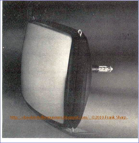
 It has a picture tube
apparatus employing the so-called delta gun shadow mask The present invention relates to a color television picture tube type color
cathode-ray tube which is provided with three electron guns positioned
respectively at the vertices of an equilateral triangle, " the so-called delta gun shadow mask ".
It has a picture tube
apparatus employing the so-called delta gun shadow mask The present invention relates to a color television picture tube type color
cathode-ray tube which is provided with three electron guns positioned
respectively at the vertices of an equilateral triangle, " the so-called delta gun shadow mask ".To obtain a fine color picture on the screen of the cathode-ray tube of this type, the following requirements should be satisfied that the electron beam is emitted from each electron gun onto the center of each corresponding phosphor dot on the screen of the cathode-ray tube, the purity of colors is high and the electron beams are converged onto a group of phosphor dots.
 These requirements can be comparatively
easily satisfied in the case of the cathode-ray tube with a spherically
formed screen, whereas it is difficult to satisfy the requirements in
the case of a narrow-necked, wide-angle deflection cathode-ray tube. The wide angle deflection cathode-ray tube is advantageous in practical
use because the distance between the electron guns and the screen is
small and the screen is almost flat with a curvature approximate to that
of a flat surface; however, it is necessary to control the electron
beams so that the electron beams may be emitted exactly onto the 3-color
phosphor dots on the screen because the incident angle and distance of
the electron beams which reach the phosphor dots on the screen have the
values proper to respective phospher dots.
These requirements can be comparatively
easily satisfied in the case of the cathode-ray tube with a spherically
formed screen, whereas it is difficult to satisfy the requirements in
the case of a narrow-necked, wide-angle deflection cathode-ray tube. The wide angle deflection cathode-ray tube is advantageous in practical
use because the distance between the electron guns and the screen is
small and the screen is almost flat with a curvature approximate to that
of a flat surface; however, it is necessary to control the electron
beams so that the electron beams may be emitted exactly onto the 3-color
phosphor dots on the screen because the incident angle and distance of
the electron beams which reach the phosphor dots on the screen have the
values proper to respective phospher dots. The total power consumption is 350 watts due to the higher deflection currents in comparison with 90° deflection colour tv sets. The set, which was sold in Germany, has such a high total power consumption because of large amount of circuits.
Some characteristics:
Nordmende Spectra-Color L2UT 4.570.D/telec.;146 Dioden, 2 Thyristoren, Hochspannungskaskade, Programmanzeige mit Leuchtziffernröhre, ACS - Buchse, Kopfhörer-TB oder HiFi Anlage, VHF/UHF-Tuner nach CCIR B/G, Fernbedienung Telecontrol 1.
Net weight (2.2 lb = 1 kg) 66.1 kg / 145 lb 9.5 oz (145.595 lb)
(To see the Internal Chassis Just click on Older Post Button on bottom page, that's simple !)
Nordmende was a manufacturer of entertainment electronics based in Bremen, Germany.
The original company, Radio H. Mende & Co, was founded in 1923 by Otto Hermann Mende
 (1885-1940) in Dresden. Following the destruction of the plant during the bombing raids in 1945, Martin Mende (the founder's son) created a new company in Bremen in 1947, in a former Focke-Wulf plant, under the name North German Mende Broadcast GmbH.
The name was subsequently changed to Nordmende: subsequently the
company became one of the prominent German manufacturers of radios,
televisions, tape recorders and record players in the 1950s and 1960s.
(1885-1940) in Dresden. Following the destruction of the plant during the bombing raids in 1945, Martin Mende (the founder's son) created a new company in Bremen in 1947, in a former Focke-Wulf plant, under the name North German Mende Broadcast GmbH.
The name was subsequently changed to Nordmende: subsequently the
company became one of the prominent German manufacturers of radios,
televisions, tape recorders and record players in the 1950s and 1960s.
In
the 1970s, Nordmende televisions were renowned for their innovative
chassis, and for the rigorous testing and quality control of their
finished products. Both created high costs, however, which soon proved a
competitive disadvantage when the price of colour televisions began to plunge.
In 1969, Mende's sons took over the company, and in 1977 a majority shareholding was sold to the French Thomson Brandt company and the chassis remains the original NordMende until CHASSIS F9. The
following year, the family sold their remaining shares to Thomson.
In the 1980s, the factories in Bremen were closed, Nordmende becoming
purely a Thomson trademark (Starting from chassis F10 F11 they're all THOMSON).
In the 1990s, the name Nordmende was used with decreasing frequency, and it eventually disappeared in favour of the Thomson name. In 2005 Videocon Group acquired all cathode ray tube activities from Thomson. This led to the creation of VDC Technologies, which manufactures TV sets using the Nordmende brand under licence from Thomson.
The Nordmende brand name was relaunched in Ireland in September 2008 by the KAL Group. Although
 Nordmende
was well known for its televisions throughout Ireland during the
1970s and 1980s, the company bought the rights to the name and
launched a range of white goods including fridges, freezers, washing machines, and dishwashers, alongside a revamped range of flat-screen TVs and stereos.
Nordmende
was well known for its televisions throughout Ireland during the
1970s and 1980s, the company bought the rights to the name and
launched a range of white goods including fridges, freezers, washing machines, and dishwashers, alongside a revamped range of flat-screen TVs and stereos.NORDMENDE HISTORY IN GERMAN:
Die Vorkriegsgeschichte findet sich unter Mende. Nach dem Totalverlust in Dresden gründet Martin Mende (30.12.1898-1982) unter Mitwirkung von Hermann Weber am 26. August 1947 [FT5901] in Bremen-Hemelingen die Norddeutsche Mende-Rundfunk GmbH.
Die ersten Gehäuse liefert ein Tischler in Achim gegen Kompensation von fünf Gehäusen zu einem Rundfunkgerät. Der frühere Mende-Konstrukteur, Obering. Heer zeichnet wieder für die Geräte verantwortlich [FT49??].
Ab 27. Juli 1948 liefert die neue, zuerst 18 und bald 60 Personen umfassende Firma auf Grund von Währungsreform, Krediten und Zulieferverträgen die neue Radioproduktion.
Das Regime in Ostdeutschland lässt den Namen Mende nicht zu, so dass Martin Mende mit grafischen Konstruktionen im Zusammenhang mit «Nord» an seinen Vorkriegserfolg anschliesst.
Die Hallen der ehemaligen Focke-Wulf AG beim Bahnhof Seebaldsbrück dienen als Werkstätten. 1950 beschäftigt das Unternehmen 700, 1959 schon 3500 und im Zenit 6300 Personen.
1950 beginnt die Firma mit UKW-, 1953 mit Fernseh- und 1954 mit Mess- und Prüfgeräten. Gegen Ende der 50er Jahre heisst die Firma Norddeutsche Mende Rundfunk KG [RP7901].
Nachdem sich Nordmende bislang nicht mit Magnettongeräten befasst hat, bringt das Werk 1958 das erste deutsche Heim-Tonbandgerät mit drei Motoren auf den Markt. Allerdings dominieren auf diesem Sektor eindeutig andere Firmen wie AEG/Telefunken und Grundig. Von Nordmende kommen jeweils nur ein bis zwei Geräte (1960 keines) in die Kataloge. Dafür hat die Firma Erfolg mit einem anderen Neueinstieg:
1958 stellt Nordmende mit «Mambo» ihr erstes Reisegerät vor - aber nicht «das erste deutsche, serienmässig hergestellte und volltransistorisierte Koffergerät», wie man aus einer Quelle nachlesen kann. Danach wird Nordmende in Deutschland auf dem Sektor Reisegeräte besonders stark, obwohl sie keine Röhren-Koffer baute. Immerhin kosten die in «Mambo» verwendeten 8 Halbleiter dann im Einzelhandel DM 98.70, während für die vier D-Röhren der 90er-Serie - auch zum Katalogpreis - etwa DM 35.- auszugeben wären. Preis des ganzen Gerätes: DM 189.- plus zwei Flachbatterien von 4,5 V.
Bis 1969 gibt es ca. 92 Modelle der tragbaren Radios (Koffer- bzw. «Handradios», d.h. «Hand held radios»). Beispielsweise finden sich im Katalog 1961/62 [448] je 11 Tischradios und Radiomöbel sowie 8 Modelle von Reiseradios. 17 verschiedene Fernsehmodelle zeigen dagegen, wo in jener Zeit der Erfolg zu holen war.
Gemäss [FT7901] liegt Nordmende während kurzer Zeit mit der sogenannten «Tippomatik-Bedienung» sogar technisch vorne. Siehe auch Philips etc.
Auch Konzertschränke scheinen Ende der 50er bis Anfang 60er Jahre eine tragende Säule für Nordmende zu sein. Dabei verwendet die Firma immer wieder gleiche Namen wie «Cabinet», «Caruso», «Casino», «Cosima» sowie «Arabella» und «Isobella» mit wechselnden Zusatz-Nummern oder den Zusatz «Stereo», z.B. in den Jahren 1959 und 1960/61.
Im März 1967 nimmt das Werk die Produktion von Farbfernsehgeräten auf. Zum Firmenjubiläum erscheint eine Gerätereihe mit der Bezeichnung 'Goldene 20'. 1969 übernehmen die Mende-Söhne Karl und Hermann die Geschäftsführung.
1977 führt der verschärfte Wettbewerb zum Verkauf der Mehrheit an den französischen Konzern Thomson-Brandt; die Familie Mende zieht sich anschliessend ganz aus dem Unternehmen zurück. Martin Mende stirbt 1982.

Weblinks:
Tote Marke NORDMENDE – Verblasster Stolz. Artikel im Manager-Magazin
Ein neues Programm. Artikel in der Zeit
Fernseher: Inder produzieren neue Nordmende. Artikel bei itespresso.de
Videocon produziert Plasmaschirme für Nordmende. Artikel im pressetext.de
Einzelnachweise
Spectra Color Studio und Spectra SK2 Color de Luxe Studio auf radiomuseum.orgMarke Nordmende mit Digital- und Internetradios zurück, teltarif.de, Artikel vom 2. September 2017.
Company profile. Phillar, archiviert vom Original am 6. März 2008; abgerufen am 26. April 2013 (englisch).
Broschüre – Sprachmanager24. Abgerufen am 5. Januar 2015.
No comments:
Post a Comment
The most important thing to remember about the Comment Rules is this:
The determination of whether any comment is in compliance is at the sole discretion of this blog’s owner.
Comments on this blog may be blocked or deleted at any time.
Fair people are getting fair reply. Spam and useless crap and filthy comments / scrapers / observations goes all directly to My Private HELL without even appearing in public !!!
The fact that a comment is permitted in no way constitutes an endorsement of any view expressed, fact alleged, or link provided in that comment by the administrator of this site.
This means that there may be a delay between the submission and the eventual appearance of your comment.
Requiring blog comments to obey well-defined rules does not infringe on the free speech of commenters.
Resisting the tide of post-modernity may be difficult, but I will attempt it anyway.
Your choice.........Live or DIE.
That indeed is where your liberty lies.
Note: Only a member of this blog may post a comment.